| Component | Part Number | # | Each | Per Unit | Source |
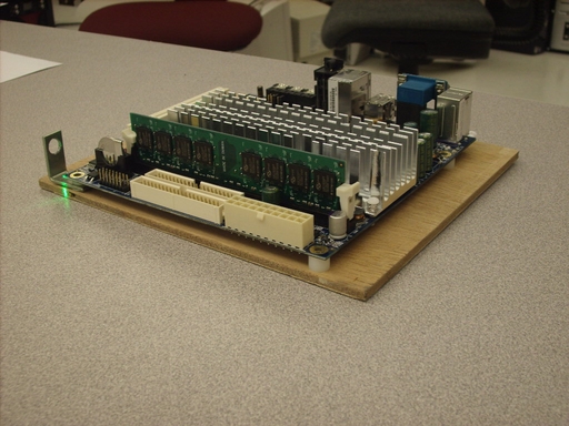
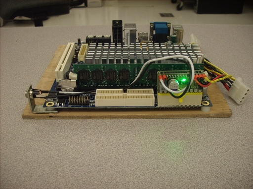
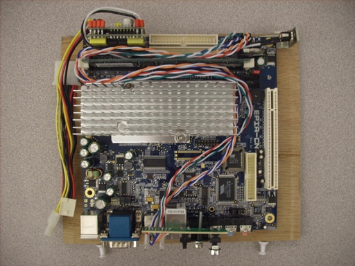
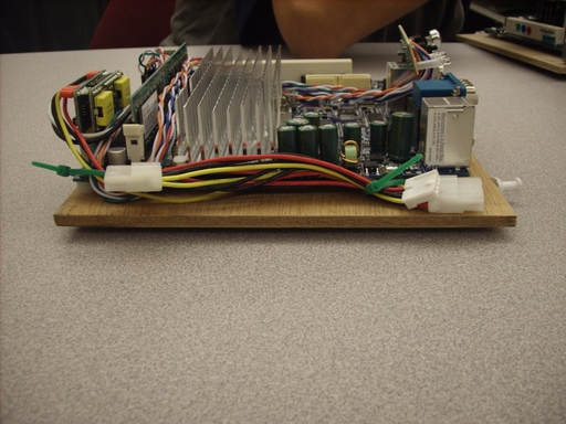
| Mainboard | VIA CN10000 | 6 | 173.00 | 1,038.00 | Logic Supply |
| Memory | DDR2 533 memory 1GB | 1 | 122.00 | 122.00 | Logic Supply |
| Memory | DDR2 533 memory 512MB | 5 | 64.00 | 320.00 | Logic Supply |
| Power supply | Pico PSU 120W | 1 | 49.00 | 49.00 | Logic Supply |
| Power supply | Pico PSU 80W | 5 | 39.00 | 195.00 | Logic Supply |
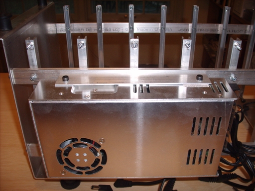
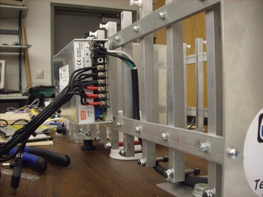
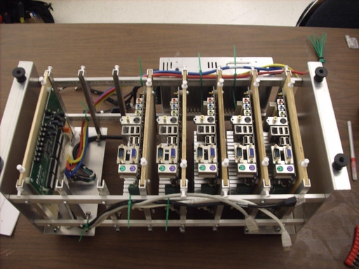
| Frame | Aluminum ends and rails | 1 | 100.00 | 100.00 | Locally Supplied |
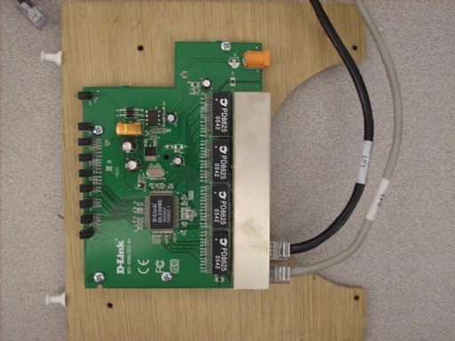
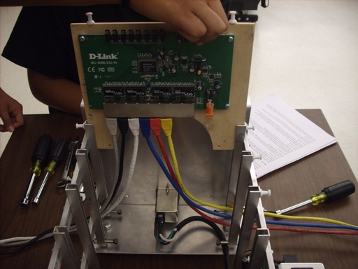
| Switch | D-Link DSS-8+ 10/100 switch | 1 | 17.00 | 17.00 | NewEgg |
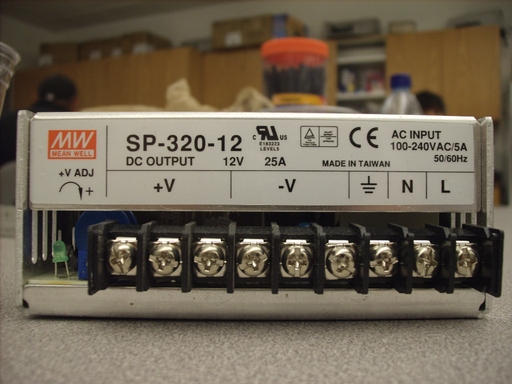
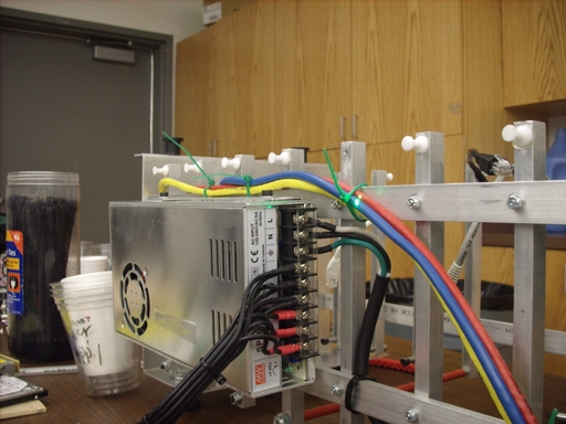
| Power supply | MeanWell SP-320-12 | 1 | 90.00 | 90.00 | PowerGate |
| Jumpers | 1 per motherboard plus 1 uplink | 7 | 2.00 | 14.00 | Locally supplied |
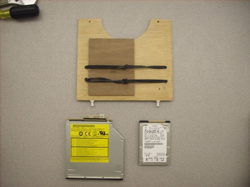
| Disk drive | Travelstar 7K100 Hitachi | 1 | 100.00 | 100.00 | Directron |
| CD drive | Panasonic CW-8124-B CD/DVD | 1 | 77.00 | 77.00 | Logic Supply |
| NIC | Low-profile 10/100 PCI card | 1 | 12.50 | 12.50 | Logic Supply |
| Well nuts | Feet for the frame | 8 | 1.65 | 13.20 | Ace Hardware |
| Aluminum | 1/2" x 1/2" angle, in feet | 12 | 1.00 | 12.00 | Ace Hardware |
| Retainers | Hitch pins | 8 | 0.12 | 0.96 | Ace Hardware |
| Standoffs | Nylon, mainboards and switch | 28 | 0.12 | 3.36 | Ace Hardware |
| 12V Input | Lead, mainboard and switch | 7 | 1.90 | 13.30 | Mouser |
| 110/220VAC | Line input and switch | 1 | 14.00 | 14.00 | Mouser |
| IDE-IDE | Motherboard to 3.5" IDE cable | 1 | 10.00 | 10.00 | Logic Supply |
| IDE-LPFF | Motherboard to 2.5" IDE cable | 1 | 10.00 | 10.00 | Logic Supply |
| Power control | Case front panel switch | 6 | 10.00 | 60.00 | Xoxide.com |
| Cards | Luan plywood mounting cards | 8 | 0.50 | 4.00 | Locally supplied |